How to make a power bank from crowns. Homemade power bank with solar battery
Sometimes, there are situations when you need to charge your phone or camera, but there is no outlet nearby. In this case, a device called a “power bank” will come to the rescue.
Such a device usually consists of a pair or three of small batteries, a charger for them and a voltage converter for the device being charged, be it a flashlight, a mobile phone or a camera.
I took the batteries from an old laptop battery, size 18650, to charge them I decided to use a Chinese TP4056 microcircuit, specially designed for charging Li-Ion batteries, and bought a boost converter built on the CE8301 chip as a ready-made module. Microcircuits and modules, ordered on eBay.com.
TP4056 has a number of positive features, namely:
1. Protect batteries from overcharging and overheating
2. A small number of external elements
3. Indication of operating modes
4.Adjustable charge current
5. Low cost
6. Etc. etc.
TP4056 connection diagram

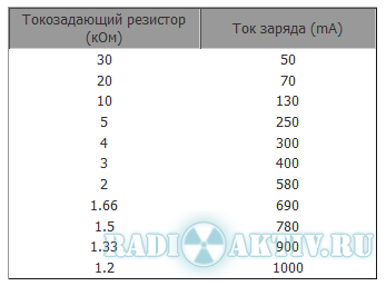
The charge current is adjusted by resistor Rprog. I set it to 2.2 kOhm, charging current 500mA.
CE8301 has a million similar analogues, you shouldn’t focus too much on it, I’ll just say that it works from 0.9V to 5V, while the output holds 5V 500mA (600mA maximum), which is quite enough to charge most mobile phones and cameras.
CE8301 connection diagram

Photos of converters

I wanted to make the finished device quite functional, so I decided to use 2 converters if I had to charge a couple of devices at once, and for batteries I decided to take as many as 4 TP4056 chips so that I could use batteries with different capacities.
To ensure that the TP4056 microcircuits do not affect each other, the batteries are connected through Schottky diodes, with a drop of 0.2 Volts.
The final diagram looked like this


Made

Checked

And installed all the components


The black droplets with the inscription 103 are 10 kOhm thermistors.
The board turned out to be quite compact, taking into account the fact that only 10 µF capacitors and TP4056 microcircuits were used from SMD components. When soldering, I placed pieces of masking (paper) tape under the housing of the microcircuits so that the heat sink of the microcircuits did not short out the tracks.
The circuit works great, nothing gets hot. During charging, the red LED lights up, when the battery voltage reaches 4.2V, the red LED goes out and the green LED lights up - charging stops. If the thermal protection has tripped, the LEDs do not light up, and if there is no battery connected to the circuit, the green light is on and the red flashes. Charging of cans of the same capacity and with the same residual voltage occurs quite synchronously. In general, I got exactly what I wanted.
Method 4. External energy storage with a solar battery
Another interesting option. As daylight hours begin to increase, it is timely to discuss the benefits of solar energy storage. You'll see how to make a portable charger that can be charged from solar energy storage panels.
We need:
- Lithium-ion energy storage 18650 format,
- Case from the same drives
- 5V 1A voltage boost module.
- Charge board for battery.
- Solar panel 5.5 V 160 mA (any size)
- Wiring for connection
- 2 diodes 1N4007 (others are possible)
- Velcro or double-sided tape for fixation
- Hot melt adhesive
- Resistor 47 Ohm
- Contacts for energy storage (thin steel plates)
- A pair of toggle switches

- Let's study the basic circuit of an external battery.
The diagram shows 2 connecting wires of different colors. Red is connected to “+”, black to “-”.
- It is not recommended to solder the contacts to the lithium-ion battery, so we will put terminals in the housing and secure them with hot glue.
- The next task is to place the voltage increase module and charging board for the battery. To do this, we make holes for the USB input and USB output 5 V 1 A, a toggle switch and wiring to the solar panel.
- We solder a resistor (resistance 47 Ohms) to the USB output, on the reverse side of the module that increases the voltage. It makes sense for iPhone charging. The resistor will solve the problem with the very control signal that starts the charging process.
- To make the panels easier to carry, you can attach the panel contacts using 2 small female-male contacts. Alternatively, you can connect the main body and panels using Velcro.
- We place a diode between 1 contact of the panel and the energy storage charge board. The diode should be placed with the arrow pointing towards the charge board. This will prevent the solar panel from draining the storage battery.
IMPORTANT. The diode is placed in the direction FROM the solar panel TO the charge board.
How many charges will this Power Bank last? It all depends on the capacity of your battery and the capacity of the gadget. Remember that discharging lithium drives below 2.7 V is highly undesirable.
As for the charge of the device itself. In our case, we used solar panels with a total capacity of 160 mAh, and the battery capacity was 2600 mAh. Therefore, under the condition of direct rays, the battery will charge in 16.3 hours. Under normal conditions - about 20–25 hours. But don't let these numbers scare you. It will charge via miniUSB in 2-3 hours. Most likely, you will use the solar panel when traveling, hiking, or long trips.
In conclusion
Choose the method that suits you best and build your own portable battery. This thing will definitely come in handy on the road or while traveling. There are a lot of advantages of the device made: it is unique appearance, and also a way to get the power that will satisfy your needs. Using a portable battery you can charge not only phones, but also tablets, wireless headphones and other small gadgets.
In everyday life, people often use gadgets (smartphones, tablets, etc.), but when we go somewhere, we constantly need to charge our phone. This problem will be solved by a Power Bank that can be made in an hour and a half from available components.
Materials and tools
Tools:- Soldering iron (solder, flux).
- Wire cutters.
- Stationery knife.
- Glue.
- Soda.
- Frame.
- - 2 pcs.
- USB (female).
- Switch.
- LED and 100 ohm resistor.

Power Bank Scheme
I assembled this Power Bank according to this scheme.
Making a Power Bank with your own hands
The first thing I did was make a battery for the future Power Bank; I made contacts from a copper bus bar. Battery capacity is about 2000 mAh.
Next, I connected two batteries in parallel to each other using sections from the busbar, but keep in mind that it is not advisable to solder the batteries, this must be done with a powerful soldering iron and very quickly so that they do not have time to heat up.

When connecting batteries, the voltage on both should be the same (4.2 volts), but it is best to charge them separately and then solder them into a battery.

I used an old one as a case doorbell, from which I first pulled out all the electronics, and I removed unnecessary protruding elements using wire cutters.

Next, I installed the USB in the place where the bell switch was previously built-in, using super glue and soda.

Using the same method, I installed a switch next to the USB.

I soldered the minus of the battery to the minus of the converter; it is advisable to use thick wires, because the currents here will be from 1 to 3 amperes, depending on what you will charge.

In the same way, I soldered the positive wire and connected the switch into the gap.

Next, I set the converter to the desired voltage, this voltage should fluctuate between 5.2 and 5.5 volts. The batteries must be fully charged when setting up.

Using a soldering iron, I made a hole for the charging controller.

I glued the controller itself with super glue and soda, why soda, because glue and soda form a durable polymer.

I will install the batteries using double-sided tape.

I installed the converter next to the controller, and also glued it with glue and soda.

Then I soldered the wires to the output of the converter, and soldered them to the USB on the outer contacts, the contacts that are in the middle, I shorted them together, this is necessary so that the phone does not mistake the Power Bank for a computer and does not charge with a current of 500 mAh.

I soldered the positive wire from the controller to one contact of the switch, and the negative wire to the input of the converter.

I cut out a diffuser for the LED from a piece of plastic and installed it between the switch and usb.

Homemade power bank - it's very simple!
I suggest you read the description of my homemade product, perhaps it will give you the impetus to make something similar with your own hands.
On at the moment A huge number of power banks of different configurations, sizes and with various additional options are available for purchase.
But I decided to assemble it myself. The reasons that prompted me were quite compelling: reluctance to spend money on a purchase (with a possible lottery), the presence of both charging boards and step-up converters up to 5 Volts. And also the presence of a huge number of batteries lying idle. The situation was aggravated by a friend who brought a dozen 18650 from a laptop.
The photo shows only a small part of the batteries. 
I bought cheap power banks for 1 element 18650 in online stores 
and bought the 18650 elements themselves, but apparently the experience was unsuccessful, or tensions with money gave rise to creativity.
Power banks for 1 cell with a capacity of up to 2600 mAh (classic case) did not allow us to fully charge a smartphone, not to mention a tablet. In addition, the batteries purchased on the Internet turned out to be fake with a real capacity of 1000 mAh. 
I bought 4 pieces, but I decided to open one to make sure it was a fake, but I accidentally shorted the poles and my battery caught fire. Fortunately, I was poking around on the balcony and, without hesitation, threw it from the 5th floor onto the street. It was winter, the temperature melted the battery from the snow and ice, and no matter how much I tried to look for it later, I never found it. That's why I found it in the spring. There are no photos, but it was a pitiful sight. What I mean is that lithium batteries require more careful handling.
I thought about the configuration of the power bank:
Frame
Initially I planned to assemble the batteries in a “pipe”, I saw something in line at a girl’s post office, but for 2-3 elements it turned out to be some kind of tube with large dimensions, which cannot be put in a pocket. It was decided to place the elements side by side (classic option). Another question arose - what should the body be made of? There was an idea to make it out of fiberglass with epoxy resin and had already started working on it, until at work with electricians I saw a plastic pipe for laying electrical wiring. 

The manufacturing process is as follows: we take 2 batteries (3-5 as many as you need), a plastic pipe and a hairdryer (construction), you can try softening the pipe in boiling water, I have not tried this option.
We wrap the batteries with several layers of electrical tape or tape. We heat the plastic pipe evenly with a hairdryer and insert the batteries. Next, the pipe cools while maintaining its shape. All that remains is to push out the batteries and part of the case is ready. Next, we remove the electrical tape (adhesive tape) from the elements so that they can be inserted freely (but without looseness) into the new housing. By the way, I didn’t succeed the first time, I stopped on the second try, but the body turned out to be a little like a propeller (I eliminated the distortion by sanding both sides).
Cut to length and sand the end with sandpaper or a file.
Next, take a piece of plexiglass, moisten it with dichloroethane (carefully poisonous) and glue it to the pipe. 
After 10 hours (dry outside or under ventilation), grind it using sandpaper or any in an accessible way. We get a glass with a bottom.
Scheme 
It can be said that there is practically none - 2 wires from the charging board to the battery, 2 wires from the boost converter board to the charging board, which, when the battery discharges to the lower level, will turn off the power to the boost converter. If you bought a boost converter board with a soldered USB connector, this simplifies the design. On a USB connector, you can connect the two middle pins to each other. Some phones use a jumper to recognize that they are connected not to a computer port but to a charger and begin to charge with an increased current (1000 mA instead of 500). I had to solder the connector on reverse side charging boards. The main nuance is to observe the polarity and try to use red wires for + (any light) and blue (any dark) for minus. Subsequently, developing the habit of using different colors simplifies life. 
There are many options, but they all come down to the use of the same microcircuits as well as field effect transistors as a battery cut-off element when discharged. Oh yes, I used the batteries without protection.
Here you will need a soldering iron to connect the boards to each other and the batteries, as well as pieces of small-section wires (the length is short, not critical).

To suit your taste and color, any one that increases up to 5 Volts and produces a current of at least 1 Ampere.
The board I use does not have protection against short circuits at the output, but I use the device for its intended purpose, so there is practically no chance of burning the converter.
A small drawback is that the converter consumes 500 µA (0.5 mA) without load, but it will take 8000 hours to discharge the batteries. Can be neglected.
There was also a need for a soldering iron. I packed the soldered board into a piece and made a hole for an LED - an indicator of the converter's operation. This was necessary for the reason that the boards in the case were not fixed in any way and it was necessary to avoid short circuits.


I recommend using used laptop batteries, cheap and cheerful.
My next power bank will be on batteries from a dead tablet.
We fix the elements together and coat them with automotive sealant, then we connect the contacts + to + and - to -, that is, in parallel.
There is a SERIOUS POINT here! Before connecting, it is necessary to bring the EMF of the elements to the same value. Let opponents write that all this is nonsense and the machinations of enemies, but from my own experience I was convinced of the need for balancing. For balancing, I prepared a 3.5 Volt flashlight bulb, but I was distracted at work and successfully forgot about balancing. I soldered both ends of the elements (soldering is performed in the presence of active flux or soldering acid; simply tinning with rosin will be problematic). You cannot warm up the soldering area for a long time - the battery may fail. The job is done, I'm waiting for the assembly from the battery to cool down, but it didn't work out that way, the structure started to burn my hand from heating, at first I thought that I had warmed it up so much with the soldering iron or damaged it, but it dawned on me - I didn't do the balancing. I quickly unsoldered it and connected + to + through the light bulb. After about 3-4 hours, I checked the current between the elements, it was no more than 5 mA, which means that the batteries have the same emf and are ready for soldering.
additional little things(USB)
To complete the design, I didn’t have enough USB port - I took it from some dead motherboard. I desoldered it in a vandal way - using a construction hair dryer.
There was an idea to use 2 USB ports and 2 converter boards at once (separate channels as expected), but there simply wasn’t enough space inside the case. and subsequently the presence of 2nd USB port was not in great demand.
Everything is fixed inside with sealant (if you like a glue gun, you can use one too) The lid is glued and made in the same way as the bottom. 


I didn’t paint the power bank, the original gray color of the body seems acceptable, nothing prevents me from sanding it and spray painting it.
After making the power bank, I thought that I shouldn’t have rushed. It was possible to use a kit from a cheap power bank and not reinvent the wheel, but then protected batteries would be required.
options to gut the cheap one, use different batteries
Some nuances in the process of making a power bank:
housing design - use of dichloroethane - poison 
It is difficult to remove shavings from plexiglass - they stick (static), it is highly advisable to select batteries from existing elements. I used charger Imax B6 
2 charge-discharge cycles with a current of 1 Ampere showed xy from xy! There were a decent number of cells with a capacity of less than 800 mAh, they went for recycling (they collect them at work and hand them over). Soldering should be done in the presence of ventilation. The batteries can be soldered with a powerful soldering iron; the boards can be soldered with a low-power one.
Tests
I recently had a trip to the city of Volgograd for the Russian F3K radio-controlled glider championship. This is where the power bank comes in handy. 32 hours on a train doesn’t seem like much, but with nothing else to do, we watched movies and played games on our smartphones and tablets. And if on the first day the sockets in the carriage were not available, then on the second day there was a queue of several hours waiting for anyone who wanted to recharge =) 
I put the power bank on charge at night when everyone was asleep, so I didn’t disturb anyone and was happy. The capacity of the power bank was enough to watch a movie and then charge the tablet at least three-quarters. 
At the hotel I left it to charge at night, during the day I used it myself and gave it to others. A completely discharged power bank charges in about 5 hours. The capacity turned out to be about 4100 mAh. The discharge current, depending on the cable, reaches 1 Ampere. When charging, the indicator lights up red, when charging is complete it turns blue. Like most 18650 charge controller boards.
When discharged, the red indicator lights up, but it is practically invisible, I did not think through the design thoroughly. 


Where would Kote be without her?

Conclusion: there are power banks with reasonable prices and better characteristics, but the presence of a 18650 mount and the desire to put your hands to it did the trick. a homemade product was born. Beta version with its shortcomings. My requests are completely covered, sometimes my daughter takes her to school.
The review was difficult, but interesting. Please point out any shortcomings. We will punish the guilty. We will encourage the rest. Missed points will be clarified and doubts will be dispelled =) I'm planning to buy +51 Add to favorites I liked the review +91 +189
In this article I will tell you how you can assemble a very cheap power bank from all sorts of rubbish that you should definitely have on hand. More precisely, something similar to a power bank, but it will perform its main function quite well. This portable charger for a smartphone will operate on a battery or Krona battery, 9 or 12 volts.
What is needed for assembly
- Ballast housing for fluorescent lamps
- Crown terminal
- Battery or battery Krona
- USB socket
- Toggle switch or button
- Voltage stabilizer 7805
- Two 100n capacitors

Preparing the case for the power bank
The ballast housing for fluorescent lamps is very convenient for such homemade products, at least for my power bank it’s just right. The crown and USB socket fit into it very well. By the way, you can take any socket; I had a broken car USB charger lying around and I took it from there. The socket is triple and installed on the board, the board itself is exactly the right size for my case, you can see this in the photo below. You can also take a single socket, make a hole for it in the case and fix it with hot glue!

So, there were a lot of unnecessary parts in my case, and using a hacksaw and a blade, I successfully got rid of them. Namely, I cut off one of the fastenings of the case with the base, and on the other side I removed only the fastening.


Next, we make a small hole in the case to output wires to the USB connector and on the other side another hole for the toggle switch. Well, or in any other place, it all depends on the size of the button used, I had a large one, so it fit right there.)


The body preparation is complete, now let's move on to assembly!
Power bank assembly
First we need to assemble a voltage stabilizer, the heart of our bank! To assemble the stabilizer I used the following diagram:
The circuit is very simple, I think it will be easy to assemble. Any 7805 can be used as a stabilizer; I took the KIA7805. We also need two 100n capacitors, but that’s basically it. We solder the circuit by surface mounting, immediately solder two thin insulated wires to the output and a terminal for the crown to the input. Please note that the terminal must be soldered into the gap on the toggle switch so that our power bank can be turned on and off!

We place the assembled circuit in the case. I glued the stabilizer with hot glue near a small hole in order to bring the wires to the USB socket.

After installing the toggle switch, I realized that the crown would not fit into one of the compartments, where it fit very well, and I had to cut off the partition.

Next, we pass the wires through a small hole and solder them to the USB socket. Be careful not to reverse the polarity!

We glue the socket itself to the end of the case using hot glue.
Closing back cover and that’s it, our bank is ready!))

It turned out very compact and neat! Believe it or not, with the help of one new Krona battery, I was able to charge a completely dead smartphone battery and recharge it a couple of times from half charge.


