DIY multi-level LED field indicator. Passive high frequency field indicators
Examples of bugs found (photo source: Internet)
It happened back in Vladivostok.
Friends, the owners of a travel agency, said that one day the cleaning lady asked them: “Why in the evening, when everyone is leaving, is there something blinking on top of your closet?” They climbed onto the cabinet, and there was almost a car battery and a walkie-talkie, secured with blue electrical tape. That's how harsh Far Eastern wiretapping was.
Battery cell phone
(fake, but still interesting) 
An unexpected find in a mobile phone that can await each of us.
In general, Samsung C4. My account died, I bought a new one. BUT, the old acc was swollen and the silhouette of a contour antenna appeared very beautifully on it - like on product tags - in stores, so that they wouldn’t take it out, I decided to find out what kind of thing it was, fortunately I wanted to throw it away anyway.I was in for a surprise.

It seemed like an ordinary battery. Carefully peel off the tape - and bang the antenna! really an antenna!
Moreover, it is designed in such a way that no matter how you get rid of it, it comes off when you try to open it. which is exactly what happened.

let's climb further. it looks like this when torn off:
1. - this is where the cable comes off.
2. - remains of the antenna.
Yes, here it is, the SS45AE chip, in theory this is all a power controller, i.e. The whole system is a wireless charging system.
BUT! look further! 
It would seem to be a common scheme for remote wireless charging, but I was intrigued by a stray - highlighted in red. It goes from the board to the account. We cut it out.
The trick is that, as I understand it, it’s some kind of piezoelectric element. When connecting it to the tester, it doesn’t show anything, but we plug it into the power supply chain - and connect it to the in-wall indicator from the tape recorder - when there are sounds - the ARROW JERKS!
Those. this element CAN work (and apparently works) AS A MICROPHONE!
In other words - the trick is this - many people ask the question: “Why is it not enough to even remove the battery so that you won’t be followed?”
Here is the answer - the bug is essentially BUILT IN into the battery! I have everything.
NSA

The CTX4000 portable radar is used as the base for all radio missions.
The radar operates in the 1-2 GHz range. The power of the internal amplifier is 2 W, the external amplifier is up to 1 kW (for comparison, the power of a standard Wi-Fi card is 0.2 W). In 2008, the CTX4000 was to be replaced by a more advanced version of PHOTOANGLO, with an extended range to 4 GHz and the size of a "small briefcase".
When turned on, the radar creates an electromagnetic field around itself (or in front of itself, depending on the type of emitter antenna) high power at the selected frequency. An informative signal from a radio bomb modulates this field, and the receiving antenna of the radio complex reads the modulated signal and, using a filter, extracts an informative signal from it (HF imposition). The radar in this scheme, as it were, organizes a communication channel between the bookmark and the receiving antenna. Recco passive avalanche sensors, or RFID cards, work in a similar way, for example.
Using a powerful external carrier signal has several advantages:
the dimensions of the antenna and the power of the emitter of the bookmark can be minimized;
a passive bookmark will consume significantly less energy (hence the size of the battery pack can also be reduced);
a passive bookmark turns on only when it is irradiated with a signal of a certain frequency, therefore identifying it is much more difficult than a regular radio bookmark.
LOUDAUTO bug 
Size: approximately 1.5 centimeters in length without batteries
Price: 30$
The sensitive microphone allows you to eavesdrop on an “office” conversation from a distance of more than 6 meters. The bug runs on a 3-volt battery and consumes so little that the battery's self-discharge currents can be greater than the bug's consumption currents. It is assembled from widely available components, so it will not be possible to connect it with the NSA (hence the “makeshift” appearance).
You can buy it for 700 rubles on aliexpress
Radio tag TAWDRYYARD 
Size: 6mm
Price: 30$
RFID tag, which is often used to determine the location of a VGA cable with a RAGEMASTER bookmark, or any other purpose. Easily detected by radar from a distance of 15 meters. Capable of operating on one standard watch battery for months or years. Made from publicly available radio components. It is planned to integrate GPS, hardware identifier and radio scanner-detector of other TAWDRYYARD bookmarks into it.
SURLYSPAWN transmitter 
Size: 9mm
Price: 30$
When irradiated by a radar, it transmits keystrokes on the keyboard of a PC or laptop to the radio in real time.
Bookmark for VGA cables RAGEMASTER 
Size: 6mm
Price: 30$
The tab is installed into the gap in the red conductor of the VGA cable.
When irradiated by a radar, the bookmark begins to emit a signal containing the current image on the monitor (only the red channel to simplify the entire circuit).
Using the NIGHTWATCH device, the attacker receives an exact copy of the image on his monitor.
Navalny's bug
“Very poor equipment,” begin experts in the field of devices for secretly obtaining information. - Once upon a time, these were mass-produced in Russia and were used en masse by law enforcement officers. But that was many, many years ago. So this is some kind of mastodon. The microphone is very large, thick wires stick out in all directions... It’s even a shame to show this to a professional, but it’s simply not decent to use. Now they listen in completely different ways.
Bug Venediktov
Bug in the prosecutor's office
One of the "bugs" was found in telephone, the second was attached to the TV wire and turned on when the plug was plugged into the socket. According to Anatoly Boyarkin, his office is checked approximately twice a year by employees of the FSB department for the Voronezh region for listening devices. The last one was carried out about six months ago, and the special services found nothing, and Boyarkin was assured that his office was out of control. “But I suspected that my office was bugged,” said the prosecutor, “so I decided to turn to independent specialists.”
Under the chevrons
“About bugs... Exactly the same ones were discovered at the end of July under the chevrons of the Slavs from the Druzhka battalion after the shelling of its base on Petrovka. Unfortunately, I don't remember all the details. The Ukrainian attack aircraft worked accurately in the mine control; a bug was accidentally discovered under the chevrons of a wounded soldier while bandaging it. My friend reported to me that the operatives found 5 or 6 more bugs exclusively in the form issued in Slavyansk at the end of April.”
TED talk
How to look for a wiretap
There are active and passive methods.The active type includes a nonlinear locator; it is something like a microwave mounted on a mine detector. When the teacher at the university turned it on, he warned that cell phones might smoke, and I started to feel a little dizzy.
Passive ones include detectors or field indicators. They react to wireless transmission. Now there are three categories of devices on the market - “toys” (up to 10,000 rubles), “business” (10-50 thousand rubles) and professional (from 100 thousand rubles)
There are bugs that, like the Chukchi, transmit what they hear. In this case, they can be detected using the “search” mode (it’s like in the movie/cartoon “Ghostbusters” they were looking for anomalies). But there are also “smart” bugs that accumulate information and send it out at a certain time. In this case, only the “monitoring” mode with recording of events and subsequent analysis will help.
a little theory about field indicators
The simplest IP (field indicator) consists of an antenna, a broadband amplifier, a threshold device and a detected signal indicating device. The operating frequency range of such an indicator is determined by the bandwidth of the broadband amplifier, and the transmitter bandwidth is usually several gigahertz. Since most PIs do not have input signal selection circuits, they are not capable of scanning frequency range and react to the appearance of electromagnetic signals exceeding the threshold value almost instantly,
regardless of transmission frequency.
For lately Selective PIs have appeared on the market, operating on the principle of a scanning receiver, but with a wider bandwidth
review. Due to the wide bandwidth, the sensitivity of the IP does not exceed 10 mV, and therefore the detection range of electromagnetic radiation exceeding the threshold value is low and in practice amounts to a few meters (“near zone”), and also strongly depends on the operating frequency and power of the radiation source . Thus, the IP registers electromagnetic radiation at the monitoring site that exceeds threshold values and, in accordance with the criteria included in the control circuit of the device, displays data about the detected signals on the display device.
Electromagnetic environment Almost any room is characterized by many components. It includes, first of all,
radiation from legal sources, which include VHF radio stations, cellular and trunking communication systems, television, radiotelephones, operating household appliances electronic equipment etc. The totality of these radiations constitutes the electromagnetic background of the room, which is used to determine the threshold level for most field indicators. The background values of electromagnetic radiation will be approximately the same for the premises adjacent to the test area.
When an active charger (stack device) is introduced into a room, its radiation in most cases will differ sharply from the background in power and amplitude and significantly exceed the threshold value. When the threshold level is correctly set, the PI will begin to detect the radiation from the charger and display the signal parameters to the display device, based on the information from which the operator will be able to make a decision about whether the identified radiation source belongs to the charger. Consequently, the information displayed on the display device plays an important role in determining whether detected emissions belong to the operation of the charger.
First, a few words about bug simulators, then about field indicators
TEST Test device

Its use allows you to evaluate the performance of the following modes:
- high-frequency detector-frequency meter;
- wire line analyzer (PLA);
- low frequency magnetic field detector;
- infrared radiation detector.
TEST is a set of simulators assembled in one case with autonomous power supply.
The simulator for assessing the performance of a high-frequency detector-frequency meter is a mini-radio transmitter with quartz frequency stabilization and the ability to turn off the modulating signal, for a wire line analyzer - a signal generator with a given frequency, for a low-frequency magnetic field detector - a source of a stable magnetic field, and for an infrared radiation detector - an IR transmitter -band with a given subcarrier frequency.
TEST allows you to evaluate the sensitivity of the path under test, the accuracy of related measurements (frequency meter, nuclear submarine synthesizer), the performance of detectors, an oscilloscope, a spectrum analyzer, and the display of measurement results.
Technical characteristics:
- Mini radio transmitter frequency, MHz - 270±0.01
- Nuclear submarine simulator frequency, MHz - 8.445
- Wavelength of the IR transmitter, nM, - within 770-1100
- Subcarrier frequency of the IR transmitter, kHz - 100
- Modulating signal frequency, kHz - 1
- Type of modulating signal - AIM
- Supply voltage, V - 3 (2 AA batteries)
- Current consumption, mA, - no more than 45
- Dimensions, mm - 88X56X18
This thing is designed for testing expensive professional field indicators, such as “Piranha”
TTM-700
I couldn’t find anything about this thing on the Internet, but the stern inscription on the body evokes respect.
Antibugs
I conducted a superficial test of the field indicators and will share the results and impressions.
BugHunter
Chips - price (about 10 thousand rubles)
A primitive interface (where you can only really select the sensitivity of the device), work only in real time (which does not allow you to detect delayed transmissions). In my clumsy hands, it either squealed all the time or detected a bug at a distance of 5-10 cm. Suitable for educational purposes, for example, for a children's camp. But if you get your hands on it, you can walk along the walls, door frames and baseboards just in case.
technical specifications
Operating frequency range - 50-3000 MHz (the entire range in which bugs and hidden cameras operate)
Sensitivity (minimum detectable field strength), - not less than 50 mV/m
Dynamic range, no less than - 48 dB
Operating modes - search, security, acoustic locking
Radio transmitter detection range 5 mW - 5 m
Cell phone detection range - 50 m

Raksa
The trick is portability. The size of a matchbox and easy to mount. The device is disguised as a car key fob.
Allows you to detect:
- cell phones of GSM900/1800, UMTS(3G), CDMA450 standards
- DECT cordless phones
- Bluetooth and Wi-Fi devices
- wireless video cameras
- radio transmitters with analog modulation (AM, FM, FM)
- radio transmitters with digital modulation and continuous carrier (FSK, PSK, etc.)
- radio transmitters with wideband modulation with a bandwidth up to 10 MHz
Peculiarities:
- selective reception of radio signals
- high scanning and analysis speed
- detection of broadband and digital signals
- adaptation to the background in security mode
- possibility of searching with spectrum subtraction
- audio control of signals
- measuring frequency and signal level
- alarm event log
- silent alarm indication (vibration signal)
- no external antenna
Security mode 
The security mode is designed for constant monitoring of detected analog and digital radio signals in automatic mode (without operator participation) and alarm signaling in the event of a dangerous radio signal, i.e. radio signal with a level exceeding the set threshold. The security mode is used in cases where initially the source of a dangerous radio signal is absent or inactive. Information about alarm events is stored in a log.
In security mode for analog signals the background spectrum is subtracted. This reduces the impact of stationary (always present) interfering signals and interference. The background spectrum adaptation algorithm monitors the slow changes in the levels of these interfering signals.
Overview Mode 
The survey mode is designed to detect analog and digital radio signals of all types. In this mode, the display shows a list of all currently detected signals, sorted by frequency or signal type.
Search mode 
Search mode is designed to detect and locate analog and digital radio transmitters. The display shows the signal with the maximum level. This mode is used in cases where it is possible to move the field indicator to search for a radio transmitter.
In the search mode for an analog signal, light and sound indication of the relative signal level is implemented - by the frequency of repetition of LED flashes, you can judge whether you are approaching or moving away from the radio transmitter.
Search mode with spectrum subtraction 
Spectrum subtraction search mode is designed to detect and locate analog radio transmitters. Using this mode has advantages over normal mode search if the radio transmitter is in the same room.
In the search mode with spectrum subtraction, it is not the absolute level of analog signals that is determined, but the relative level - its difference with the base spectrum, which was measured at the beginning of work in this mode. It is known that when approaching or moving away from a radio transmitter located indoors, the signal level changes more strongly compared to a radio transmitter located outdoors. Because In the spectrum subtraction search mode, the field indicator selectively responds to level changes, local radio transmitters are more likely to be detected.
In the search mode with spectrum subtraction, light and sound indication of the relative signal level is implemented.
Digital Signal Monitoring 
The digital signal monitoring mode is designed to detect signals from cell phones of the GSM900/1800, UMTS(3G), CDMA450, cordless phones DECT standard Bluetooth devices, Wi-Fi and other pulse signals in the 2.4 GHz range. In digital signal monitoring mode, the display shows a list of all digital signals and their detected levels
Alarm event log 
The alarm event log stores information about dangerous radio signals that were detected in security mode. The maximum number of entries is 200. If dangerous signals are detected at the same time different types, then the log stores information about each of them. When viewing a recording, the display shows the time the signal appears and disappears, its type and maximum level.
Specifications:
- received range: frequencies 50-3200 MHz
- typical sensitivity: 70 mV/m
- dynamic range: 50 dB
- Bandwidth: 10 MHz
- time full cycle scanning: 1.5 s
- operating time in security mode: 4-12 hours.
- operating time in other modes: 3 hours.
- display: OLED, 128 x 64
- dimensions: 77 x 43 x 18 mm
- weight: 35 g
The TTM-700 bug simulator can be detected at a distance of 30-40 cm using a normal search, and at a distance of 60-70 cm in the “search with subtraction” mode.
I discovered the TEST simulator from a distance of 20-25 cm in the search mode, in the “search with subtraction” mode - 35-40 cm
ST 110
Chips - the coolest settings system, work without false positives. Oscilloscope mode. PC compatible.
In general, the device looks and is made like a serious military device.
Two operating modes:
- search for radio microphones (bugs) in premises
- monitoring radio microphones for visitors who come to your office or for negotiations outside the office.
An additional HF antenna extends the frequency range to 7000 MHz.
What does it find?
- radio microphones;
- telephone radio repeaters;
- radio stethoscopes;
- hidden video cameras with information transmission via radio channel;
- technical means of spatial high-frequency irradiation systems;
- radio beacons for tracking systems;
- cell phones, radios and cordless phones.
SEARCH mode:
This mode is intended for rapid search and determination of the location of the RTS. The use of this mode is based on a visual assessment of the signal level on a 32-segment scale for each frequency range. Additionally, separate indication of continuous and pulse types of signals is used, display of identified signals - GSM, DECT, BLUETOOTH and 802.11g, as well as indication of the frequency of a stable signal.
There are “smart bugs”, there is a regime against him -
MONITORING mode:
Designed to detect RTS based on a specified threshold, frequency or type of signal. At battery life Information is stored in the non-volatile memory of the product (9 banks of 999 events each).
Ensured work according to schedule.
PROTOCOL VIEW mode:
Designed to view the log of events that occurred as a result of product operation in MONITORING mode.
It is possible to sort events according to the following criteria: time of occurrence of the event, duration of the event, signal level and frequency range.
OSCILLOSCOPE mode
- Installation option (A - automatic P - manual) and relative vertical scan value (from 1 to 7)
- Oscillogram
- Horizontal scan value in terms of the entire screen (from 1, 2,4,8, 16 and 32ms)
- display in graphical form the result of ST 110 operation in real time;
- loading and display, both graphically and text format the result of ST 110 operation in the “Monitoring” mode (event log);
- Full control of ST 110 from a PC.
technical specifications
Main unit
Frequency range, MHz - 50-2500
Threshold sensitivity at input, no more than, dBm:
minus 75 (50 MHz)
minus 70 (1500 MHz)
minus 50 (2500 MHz)
Dynamic range of indication, dB:
55 (50-2000 MHz)
40 (2000-2500 MHz)
Frequency meter sensitivity, dBm:
minus 35 (50 MHz)
minus 50 (500 MHz)
minus 20 (2500 MHz)
Frequency measurement error, % - 0.005
Low-pass filter cutoff frequency, MHz - 750
Internal power supply - Li-pol acc. battery
Current consumption, mA, no more than - 65
Dimensions, mm - 90x54x21
Weight, kg, no more than - 0.15
Microwave antenna – detector ST110.SHF
Frequency range, MHz - 2000-7000
Threshold sensitivity, W/cm2 - (2-9)*10-10
Dynamic range, dB - 45
Current consumption, mA, no more than - 25
Dimensions, mm - D=72, L=16

Price: 28,000 rub.
I detected the TTM-700 bug simulator at a distance of 150 - 170 cm, TEST at a distance of 45-50 cm.
Conclusion
- The baghunter may find something, but only in clear air is a powerful transmitter (like a tall tree in an open field), but in modern industrial conditions it is quite useless
- Raksa is good in your pocket during negotiations
- The ST-110 is good for searching in complex electromagnetic environments and for searching for difficult-to-detect transmitters
Security equipment and information protection
With a minimum of details and the absence of active components, it really shows the field level, and not possible problems with its electronic circuit.
The main element for the manufacture of a high-frequency radiation indicator is an ultra-high-frequency detector diode. Old (most likely point) microwave diodes such as D405, D602 or similar, Schottky microwave detector diodes KA202-KA207, imported microwave detector diodes can be used as such a diode. As a last resort, you can take a germanium diode like D311 for testing, but its operating frequency will not exceed 100 MHz.
The main difference between a detector diode is that the direct branch of its current-voltage characteristic begins to rise almost immediately from 0 V.
Attention. Under no circumstances should you measure microwave diodes with a tester.
Indicator schemes


Rice. 4.6. Field indicators: a - circuit diagram passive field indicator; b-circuit diagram field indicator with sound indication; c - schematic diagram of a simple UHF for a field indicator; r-circuit diagram broadband stable UHF for field indicator
Those who are curious and do not have a curve graph can characterize the diode manually using a voltmeter and milliammeter, applying a forward voltage to the diode in 0.05 V increments and limiting the direct current through it to no more than 0.5 mA.
When the diode is found, you can begin making the indicator. Actually, the indicator itself is a dial microammeter RA1 with a current measurement limit of 30-50 μA. Silicon diodes VD1, VD2 protect the detector and indicator from overload.
The WA1 antenna can be wire “whiskers” made of copper wire with a diameter of 1-2 mm and a length of 200-300 mm or two telescopic antennas. For greater sensitivity of the indicator, the length of the antenna should be close to the half-wavelength of the measured radiation.
Using a passive field indicator, it is convenient to study the behavior of transmitters and evaluate the radiation patterns of antennas, but a passive indicator is inconvenient for inspecting premises. It has low sensitivity when waving such an indicator, so it is difficult to see a change in the position of the instrument’s needle, and the highly sensitive pointer microammeter itself really does not like shocks and impacts.
For ease of use, you have to surround the microwave detector electronic circuit(Fig. 4.6, b). The circuit provides light and sound indication of the field strength level.
The change in field strength can be estimated from the repetition frequency sound signals with a duration of 0.2 ms and a frequency of about 1 kHz or flashes of the VD4 LED.
The number of signals varies from one every tens of seconds to a continuous tone at a high signal level. An audio indication that allows you to evaluate the current level of RF radiation and a sensitivity control allow you to quickly and effectively localize the source of radio radiation.
The first op-amp DA1.1 is a non-inverting amplifier DC, the gain of which is regulated by resistor R3, combined with a switch. The next two stages on DA 1.2, DA1.3 are built according to the same type of controlled multivibrator circuit using an op-amp. The repeater on DA1.4 serves as a ground level driver. DA1.3 contains a multivibrator controlled by high-level voltage, its frequency is about 1000 Hz. The audio multivibrator is launched from a voltage-controlled generator made on DA1.2.
Positive pulses of the generator do not depend on the level of the input signal; their duration of about 0.2 s is set by chain R8, NW. The duration of pauses between pulses depends on the discharge rate of the SZ through transistor VT1 and resistor R6. And the conductivity of transistor VT1, in turn, depends on the input RF voltage rectified by the detector VD1 and increased by the DC amplifier on DA1.1. DA1 is a quad operational amplifier with an input range that includes zero input voltage.
If the sensitivity of the indicator seems insufficient, then in front of VD1 you can turn on a broadband high-frequency amplifier made according to the circuit shown in Fig. 4.6, c or fig. 4.6, g.
To ensure that broadband UHF does not excite and has a uniform frequency response, it must be designed in accordance with the design requirements of high-frequency devices.
Advice. It is advisable to take transistors for UHF with a cutoff frequency of at least 4 GHz.
The device is equipped with a telescopic antenna WA1 and is powered by a nine-volt battery. Variable resistor R3, combined with power switch SA1, regulates the sensitivity of the device. It is set in such a way that an increase in the field strength level causes the most dramatic change in the repetition rate of the indication pulses.
The designs described in the article electric field indicators can be used to determine the presence of electrostatic potentials. These potentials are dangerous for many semiconductor devices(microcircuits, field-effect transistors), their presence can cause an explosion of a dust or aerosol cloud. Indicators can also be used to remotely determine the presence of high-tension electric fields (from high-voltage and high-frequency installations, high-voltage electrical power equipment).
Field-effect transistors are used as the sensitive element of all designs, the electrical resistance of which depends on the voltage on their control electrode - the gate. When an electrical signal is applied to the control electrode field effect transistor the drain-source electrical resistance of the latter changes noticeably. Accordingly, the amount of electric current flowing through the field-effect transistor also changes. LEDs are used to indicate current changes. The indicator (Fig. 1) contains three parts: field-effect transistor VT1 - electric field sensor, HL1 - current indicator, zener diode VD1 - field-effect transistor protection element. A piece of thick insulated wire 10...15 cm long was used as an antenna. The longer the antenna, the higher the sensitivity of the device.

The indicator in Fig. 2 differs from the previous one in the presence of an adjustable bias source on the control electrode of the field-effect transistor. This addition is explained by the fact that the current through the field-effect transistor depends on the initial bias at its gate. For transistors of even the same production batch, and even more so for transistors of different types, the value of the initial bias to ensure equal current through the load is noticeably different. Therefore, by adjusting the initial bias on the transistor's gate, you can set both the initial current through the load resistance (LED) and control the sensitivity of the device.
The initial current through the LED of the considered circuits is 2...3 mA. The next indicator (Fig. 3) uses three LEDs for indication. IN original condition(in the absence of an electric field) the resistance of the source-drain channel of the field-effect transistor is small. The current flows predominantly through the device's on state indicator - the green LED HL1.

This LED bypasses a chain of series-connected LEDs HL2 and HL3. In the presence of an external above-threshold electric field, the resistance of the source-drain channel of the field-effect transistor increases. The HL1 LED turns off smoothly or instantly. The current from the power source through the limiting resistor R1 begins to flow through the red LEDs HL2 and HL3 connected in series. These LEDs can be installed to the left or right of HL1. High-sensitivity electric field indicators using composite transistors are shown in Figs. 4 and 5. The principle of their operation corresponds to the previously described designs. The maximum current through the LEDs should not exceed 20 mA.

Instead of the field-effect transistors indicated in the diagrams, other field-effect transistors can be used (especially in circuits with adjustable initial gate bias). Zener protection diode can be used of another type with a maximum stabilization voltage of 10 V, preferably symmetrical. In a number of circuits (Fig. 1, 3, 4), the zener diode, to the detriment of reliability, can be excluded from the circuit. In this case, in order to avoid damage to the field-effect transistor, the antenna must not touch a charged object; the antenna itself must be well insulated. At the same time, the sensitivity of the indicator increases noticeably. The zener diode in all circuits can also be replaced with a resistance of 10...30 MOhm.

I was very surprised when my simple homemade detector-indicator went off scale next to a working microwave oven in our work canteen. It’s all shielded, maybe there’s some kind of malfunction? I decided to check out my new stove; it had hardly been used. The indicator also deviated to the full scale!
 I assemble such a simple indicator in a short time every time I go to field tests of transmitting and receiving equipment. It helps a lot in work, you don’t have to carry a lot of equipment with you, it’s always easy to check the functionality of the transmitter with a simple homemade product (where the antenna connector is not fully screwed in, or you forgot to turn on the power). Customers really like this style of retro indicator and have to leave it as a gift.
The advantage is the simplicity of the design and the lack of power. Eternal device.
It’s easy to do, much easier than exactly the same “” medium wave range. Instead of a network extension cord (inductor) - a piece of copper wire; by analogy, you can have several wires in parallel, it won’t be any worse. The wire itself in the form of a circle 17 cm long, at least 0.5 mm thick (for greater flexibility I use three such wires) is both an oscillating circuit at the bottom and a loop antenna for the upper part of the range, which ranges from 900 to 2450 MHz (I did not check the performance above ). It is possible to use a more complex directional antenna and input matching, but such a deviation would not correspond to the title of the topic. A variable, built-in or just a capacitor (aka a basin) is not needed, for a microwave there are two connections next to each other, already a capacitor.
There is no need to look for a germanium diode; it will be replaced by a PIN diode HSMP: 3880, 3802, 3810, 3812, etc., or HSHS 2812 (I used it). If you want to move above the frequency of the microwave oven (2450 MHz), choose diodes with a lower capacitance (0.2 pF), HSMP -3860 - 3864 diodes may be suitable. When installing, do not overheat. It is necessary to solder spot-quickly, in 1 second.
Instead of high-impedance headphones there is a dial indicator. The magnetoelectric system has the advantage of inertia. The filter capacitor (0.1 µF) helps the needle move smoothly. The higher the indicator resistance, the more sensitive the field meter (the resistance of my indicators ranges from 0.5 to 1.75 kOhm). The information contained in a deviating or twitching arrow has a magical effect on those present.
Such a field indicator, installed next to the head of a person talking on a mobile phone, will first cause amazement on the face, perhaps bring the person back to reality, and save him from possible diseases.
If you still have strength and health, be sure to point your mouse at one of these articles.
Instead of a dial gauge, you can use a tester that will measure DC voltage at the most sensitive limit.
 |
| Microwave indicator circuit with LED. |
 |
| Microwave indicator with LED. |
Tried it LED as indicator. This design can be designed in the form of a keychain using a flat 3-volt battery, or inserted into an empty mobile phone case. The standby current of the device is 0.25 mA, the operating current directly depends on the brightness of the LED and will be about 5 mA. The voltage rectified by the diode is amplified by the operational amplifier, accumulated on the capacitor and opens the switching device on the transistor, which turns on the LED.
If the dial indicator without a battery deviated within a radius of 0.5 - 1 meter, then the color music on the diode moved up to 5 meters, both from the cell phone and from the microwave oven. I was not mistaken about color music, see for yourself that the maximum power will only be when talking on a mobile phone and in the presence of extraneous loud noise.
Adjustment.
I collected several such indicators, and they worked immediately. But there are still nuances. When turned on, the voltage on all pins of the microcircuit, except the fifth, should be equal to 0. If this condition is not met, connect the first pin of the microcircuit through a 39 kOhm resistor to minus (ground). It happens that the configuration of microwave diodes in the assembly does not coincide with the drawing, so you must adhere to electrical diagram, and before installation, I would advise you to ring the diodes for their compliance.
For ease of use, you can worsen the sensitivity by reducing the 1 mOhm resistor, or reducing the length of the wire turn. With the given field ratings, microwave base telephone stations can be sensed within a radius of 50 - 100 m.
With such an indicator, you can draw up an environmental map of your area and highlight places where you can’t hang out with strollers or stay with children for a long time.
 |
Be under base station antennas |
Analog level indicator.

I decided to try to make the microwave indicator a little more complex, for which I added an analog level meter to it. For convenience, I used the same element base. The circuit shows three DC operational amplifiers with different gains. In the layout, I settled on 3 cascades, although you can plan a 4th one using the LMV 824 microcircuit (4th op-amp in one package). Having used power from 3, (3.7 telephone battery) and 4.5 volts, I came to the conclusion that it is possible to do without a key stage on a transistor. Thus, we got one microcircuit, a microwave diode and 4 LEDs. Taking into account the conditions of strong electromagnetic fields in which the indicator will operate, I used blocking and filtering capacitors for all inputs, feedback circuits and op-amp power supply.
Adjustment.
When turned on, the voltage on all pins of the microcircuit, except the fifth, should be equal to 0. If this condition is not met, connect the first pin of the microcircuit through a 39 kOhm resistor to minus (ground). It happens that the configuration of microwave diodes in the assembly does not coincide with the drawing, so you need to adhere to the electrical diagram, and before installation, I would advise you to test the diodes for their compliance.
This prototype has already been tested.
The interval from 3 lit LEDs to completely extinguished ones is about 20 dB.
Power supply from 3 to 4.5 volts. Standby current from 0.65 to 0.75 mA. The operating current when the 1st LED lights up is from 3 to 5 mA.
This microwave field indicator on a chip with a 4th op amp was assembled by Nikolai.
Here is his diagram.
 |
| Dimensions and pin markings of the LMV824 microcircuit. |
 |
| Installation of microwave indicator on the LMV824 chip. |
The MC 33174D microcircuit, which has similar parameters and includes four operational amplifiers, is housed in a dip package and is larger in size and therefore more convenient for amateur radio installation. The electrical configuration of the pins completely coincides with the L MV 824 microcircuit. Using the MC 33174D microcircuit, I made a layout of a microwave indicator with four LEDs. A 9.1 kOhm resistor and a 0.1 μF capacitor in parallel with it are added between pins 6 and 7 of the microcircuit. The seventh pin of the microcircuit is connected through a 680 Ohm resistor to the 4th LED. The standard size of the parts is 06 03. The breadboard is powered by a lithium cell of 3.3 - 4.2 volts.
 |
| Indicator on the MC33174 chip. |
 |
| Reverse side. |

The original design of the economical field indicator is a souvenir made in China. This inexpensive toy contains: a radio, a clock with a date, a thermometer and, finally, a field indicator. The unframed, flooded microcircuit consumes negligibly little energy, since it operates in timing mode; it reacts to the activation of a mobile phone from a distance of 1 meter, simulating a few seconds of LED indication of an emergency alarm with headlights. Such circuits are implemented on programmable microprocessors with a minimum number of parts.
Addition to comments.
Selective field meters for the amateur band 430 - 440 MHz
and for the PMR band (446 MHz).
Indicators of microwave fields for amateur bands from 430 to 446 MHz can be made selective by adding an additional circuit L to SK, where L to is a turn of wire with a diameter of 0.5 mm and a length of 3 cm, and SK is a trimming capacitor with a nominal value of 2 - 6 pF . The turn of wire itself, as an option, can be made in the form of a 3-turn coil, with a pitch wound on a mandrel with a diameter of 2 mm with the same wire. An antenna in the form of a piece of wire 17 cm long must be connected to the circuit through a 3.3 pF coupling capacitor.
 |
| Range 430 - 446 MHz. Instead of a turn, there is a step-wound coil. |
 |
| Diagram for ranges 430 - 446 MHz. |
 |
| Frequency range mounting 430 - 446 MHz. |
By the way, if you are serious about microwave measurements of individual frequencies, you can use selective SAW filters instead of a circuit. In the capital's radio stores their assortment is currently more than sufficient. You will need to add an RF transformer to the circuit after the filter.
But this is another topic that does not correspond to the title of the post.
Almost every novice radio amateur has tried to assemble a radio bug. There are quite a few circuits on our website, many of which contain only one transistor, a coil and a harness - several resistors and capacitors. But even so simple diagram It will not be easy to configure correctly without special equipment. We won’t talk about the wave meter and HF frequency meter - as a rule, beginning radio amateurs have not yet acquired such complex and expensive devices, but assembling a simple HF detector is not just necessary, but absolutely necessary.
Below are the details for it.

This detector allows you to determine whether there is high-frequency radiation, that is, whether the transmitter generates any signal. Of course, it will not show the frequency, but for this you can use a regular FM radio receiver.

The design of the RF detector can be any: wall-mounted or a small plastic box in which a dial indicator and other parts will fit, and the antenna (a piece of thick wire 5-10 cm) will be brought out. Capacitors can be used of any type; deviations in part ratings are permissible within a very wide range.

RF Radiation Detector Parts:
- Resistor 1-5 kilo-ohms;
- Capacitor 0.01-0.1 microfarad;
- Capacitor 30-100 picofarads;
- Diode D9, KD503 or GD504.
- Pointer microammeter for 50-100 microamps.
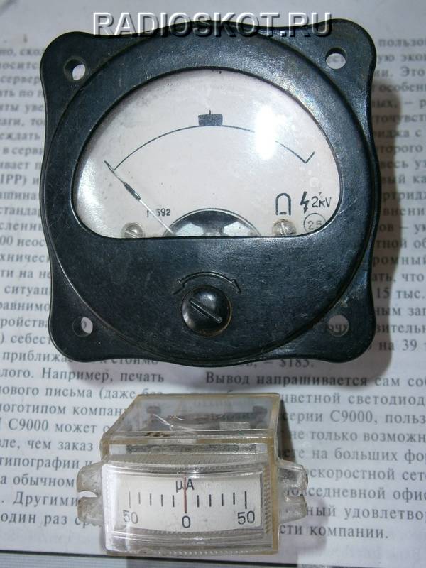
The indicator itself can be anything, even if it is for high current or voltage (voltmeter), just open the case and remove the shunt inside the device, turning it into a microammeter.
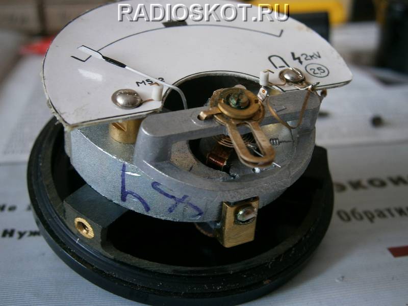
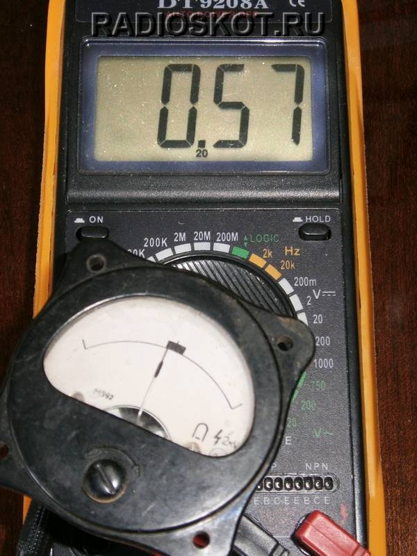
If you do not know the characteristics of the indicator, then to find out what current it is at, simply connect it to an ohmmeter first at a known current (where the marking is indicated) and remember the percentage of scale deviation.

And then connect an unknown pointer device and by the deflection of the pointer it will become clear what current it is designed for. If a 50 µA indicator gives a complete deviation, and an unknown device at the same voltage gives a half deviation, then it is 100 µA.
For clarity, I assembled a surface-mounted RF signal detector and measured the radiation from a freshly assembled FM radio microphone.

When the transmitter circuit is powered from 2V (severely shrunken crown), the detector needle deviates by 10% of the scale. And with a fresh 9V battery - almost half.

Please note that the probe does not touch the antenna or board; it catches RF radiation at a certain distance. If you poke the detector into the antenna soldering area, it will go off scale. In this way, you can determine the performance of the circuit of any transmitter with a frequency of up to 500 MHz.

For more high frequencies you should use another one, a little more complex circuit HF detector. But for the 108 MHz FM band it is enough.
Discuss the article RADIATION DETECTOR


