Make a remote control for a man with your own hands. A simple DIY IR remote control system
I recently purchased it from a well-known site - the online store Dilextream, another interesting device, which is a set of a control panel and a receiving unit connected to the network and load break. This is intended for radio control of any household appliance - a motor, lighting lamps, a fan, a garage door with a motor. In general, the meaning comes down to the fact that the control panel can give the command ON - turn on (supply) power to the device and OFF - turn off the power.
The remote control itself is simple but convenient. It is made in the form of a small keychain with a carabiner, and contains 2 buttons for turning on and off the load - the executable device.
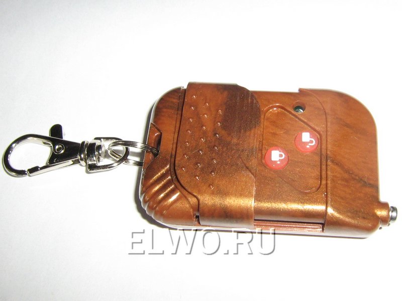
Separate controls, rather than one on/off button, are made to prevent false positives when you accidentally press the remote control button repeatedly. Moreover, the buttons are closed with a movable lid, which completely eliminates unexpected pressing.

If you use the device in conditions of strong radio interference, you can increase the range of the radio channel by extending the small telescopic antenna on the key fob. Then, under direct visibility conditions, the range will double.

Remote controller remote control It is powered by a 12 V battery, which is usually installed in the remote control of car alarms.

Inside, the key fob is also very similar to the scarf of a car alarm remote control, which allows us to draw a conclusion about the identity of the circuit design, and, accordingly, about the level of protection.

When you press any button, the red LED flashes briefly - to make it clear: the battery is working and the signal is transmitted to the receiving part.

The transmitter power is quite high - the photo shows the deflection of the needle of a simple RF probe, and the radio channel frequency is about 315 megahertz.

The receiver of the remote load control device is made according to the classical scheme with a small planar RF module (according to the super-regenerative receiver scheme) and a decoder on the SC2272-L4. can be viewed here.


The load is controlled by a 250 V 5 A relay, which makes it possible to switch a maximum of 1 kilowatt.
In the century modern technologies and technological progress, it is difficult to imagine your life without a TV, which is controlled by a remote control. But what to do if the remote control is broken?
Of course, you can go to the store and buy a new remote control, but not everyone has the opportunity to do this immediately. If for some reason a person does not want to buy a new remote control, there is a simple solution: you can make the remote control yourself.
With the advent of smartphones, assembling a remote control with your own hands has become easier than ever and anyone can do it at home. But the main thing is that such a remote control can control any TV that has an IR port, as well as other household appliances.
To turn your smartphone into remote control TV controls you will need:
- phone with Android OS;
- 2 infrared diodes (they can be taken from old remote controls);
- sandpaper;
- superglue;
- soldering iron;
- wire cutters;
- plug (can be from headphones).
Build process
When starting to assemble the remote control, make sure that all the necessary tools and parts listed above are at hand. Assembly consists of several stages:
- Grind off the protruding side parts of the IR diodes on one side only with sandpaper;
- Glue 2 diodes together with superglue, pressing one element to the other with the smooth (ground) side. Wait for the glue to dry;
- Bend the legs of the diodes and bite off the excess parts with wire cutters;
- Solder the anode of one diode to the cathode of the other with a soldering iron. Do the same with the second IR diode;
- Then you need to solder the LEDs to the plug legs; the polarity when soldering is not important at this stage;

- Fill the soldering area with glue and wrap it with electrical tape;
- Insert the resulting device into the headphone jack;
- Download a program to control your TV from the Play Store and install it on your phone.
As you can see, there is nothing complicated in assembling a remote control for a TV; for this you do not need to have a higher education or be a radio physicist.
Which application should I choose and set up to control my TV?
Many phone manufacturers have developed their own applications to control smartphones as a remote control, intended only for their models. The choice of application mainly depends on the phone model, but there are also universal programs for Android that are suitable for any smartphone.

Consider the TV Remote Control application, which has a free license and runs on Android 2.2 or higher
The program has a simple interface and, despite the lack of Russian language in it, it is very easy to understand. To control your smartphone as a remote control, use TV Remote Control to simple settings, namely:
- Select the IR Port connection mode (you can select other modes, for example, via Wi Fi or IR Blaster);
- Select your TV model;
- Confirm your choice.
Hi all. I present for general viewing a homemade radio control panel for controlling various objects from a distance. It could be a car, a tank, a boat, etc. made by me for a “children’s” radio circle. Using the NRF24L01 radio module and ATMEGA16 microcontroller.
For a long time I had a box of identical broken game joysticks from consoles. Got it from a gaming establishment. I haven’t seen any particular use for faulty game joysticks, and it’s a shame to throw them away or disassemble them. So the box stood like a dead weight collecting dust. The idea of using gaming joysticks came as soon as I talked to my friend. A friend led a group for young radio amateurs at the boarding school, free of charge on weekends, he introduced inquisitive children to the world of radio electronics. Children are like sponges, absorbing information. Since I myself really welcome such circles for children, and here also in such a place. So he suggested an idea on how to use non-working joysticks. The idea was the following: to create a homemade radio remote control for models assembled with your own hands, which I would like to offer to children to study the project. He really liked the idea, considering that funding for children's institutions is, to put it mildly, not very good, and I was also interested in this project. Let me also make my contribution to the development of the radio circle.
The goal of the project is to create a complete device not only as a radio remote control, but also as a response to a radio-controlled object. Considering that the remote control is for children, connecting the receiving part to the model should also be as simple as possible.
Assembly and components:

Having disassembled the game joystick into its components, it immediately became clear that we needed to make a new printed circuit board, and of a very unusual shape. At first, I wanted to connect the printed circuit board to the ATMEGA48 microcontroller, but as it turned out, there simply weren’t enough microcontroller ports for all the buttons. Of course, in principle, such a number of buttons is not needed and it was possible to limit ourselves to only four ADC microcontroller ports for two joysticks and two ports for clock buttons located on the joysticks. But I wanted as much as possible large number buttons to use, who knows what else the kids will want to add. This is how the printed circuit board for the ATMEGA16 microcontroller was born. I had the microcontrollers themselves, left over from some project. 
The rubber bands on the buttons were very worn out and could not be restored. But this is not surprising considering where joysticks were used. For this reason, I used tact buttons. Perhaps the disadvantages of tact buttons include the strong clicking sound that occurs as a result of pressing the button. But for this project it is very tolerable.
The board with joysticks did not have to be redone, I left it as is, which saved a lot of time. The end buttons were also kept in their original form.
I chose the NRF24L01 radio module as the transceiver, since the price is very low in China at $0.60 per piece. bought. Despite its low cost, the radio module has considerable capabilities and of course suited me. The next problem I encountered was where to place the radio module. There is not enough free space in the case, for this reason the radio module was placed in one of the handles of the joystick case. There was no need to even fix it; the module was pressed tightly when the entire body was assembled.

Perhaps the biggest problem was the issue of power supply for the radio remote control. The purchase of some specialized batteries, say lithium ones, cost a pretty penny, since it was decided to assemble seven sets. And the rest free space the case did not really allow the use of standard AA batteries. Although the consumption is not significant, various suitable power sources can be used. As always, friendship came to the rescue; a colleague at work fitted lithium flat batteries from mobile phones and a charging bonus for them. Still, I had to redo them a little, but this is insignificant and much better than making battery charging from scratch. That's where I settled on flat lithium batteries.
During testing, the radio module justified its declared range and worked reliably in line of sight at a distance of 50 meters; through walls, the range decreased significantly. There were also plans to install a vibration motor that would react, say, to some collisions or other actions in radio controlled model. In this regard, I have provided for printed circuit board transistor switch for control. But I left additional complications for later. First, I need to test the program, since it is still raw. And the design, considering that this is a prototype requires minor modifications. That’s how they say, “one by one,” a radio control panel was created with almost minimal investment.
The remote control of a VCR, TV, stereo system or satellite receiver Can be used to turn off and on various household electrical appliances, including lighting.
Do-it-yourself remote control, the diagram of which is given in this article, will help us with this.
Description of the operation of the IR remote control system
The following mechanism is used to remotely control devices. Press and hold an arbitrary button on the remote control for 1 second. The system does not respond to a short press (for example, when operating a music center).
In order to prevent the TV from responding to the control of devices, you must select unused buttons on the remote control or use the remote control from the device that is turned off at this time.
The schematic diagram of the remote control is shown in Figure 1. A special microcircuit DA1 amplifies and forms the electrical signal of the photodiode BL1 into electrical pulses. A comparator is built on radioelements DD1.1 and DD1.2, and a pulse generator is built on radioelements DD1.3, DD1.4.
The state of the control system (load on or off) is controlled by trigger DD2.1. If the direct output of this trigger is log 1, the generator will operate at a frequency of approximately 1 kHz. Pulses will appear at the emitters of transistors VT1 and VT2, which will go through capacitance C10 to the control pin of triac VS1. It will unlock at the beginning of each half-cycle of the mains voltage.
In the initial position, on pin 7 of the DA1 microcircuit there is log 1, capacitance C5 is charged through resistances R1, R2 and at the input C of the DD2.1 trigger, log 0. If IR radiation signals from the remote control are sent to the photodiode BL1, at pin 7 of the DA1 microcircuit there will be signals, and capacitance C5 will be discharged through diode VD1 and resistance R2.
When the potential at C5 drops to the lower level of the comparator (after 1 second or more), the comparator will switch and a signal will be sent to the input of the trigger DD2.1. The state of trigger DD2.1 will change. This is how devices switch from one state to another.

Microcircuits DD1 and DD2 can be used similar from the K564, K176 series. VD2 is a zener diode for a voltage of 8-9 volts and a current of more than 35 mA. Diodes VD3 and VD4 - KD102B or similar. Oxide containers - K50-35; C2, C4, C6, C7 - K10-17; C9, C10 - K73-16 or K73-17.
Setting up the IR remote control system
It consists in selecting resistance R2 of such a value that switching occurs in 1...2 s. If increasing the value of this resistance leads to the fact that capacitance C5 will not discharge to the threshold voltage, it is necessary to double capacitance C5 and make the adjustment again.
Capacitance C6 should be installed if the duration of the front of the pulse coming from the comparator to the trigger is excessively long and it switches unstably.
If the remote control used does not allow you to control the device without interfering with the TV, it is possible to assemble a homemade remote control, which is a generator of rectangular signals with a repetition frequency of 20...40 kHz, operating on an IR emitting diode. Variants of a similar remote control on the KR1006VI1 timer (
Good day to all, dear friends! In today's article I would like to show you a rather interesting and simple homemade product, namely remote switch. For it we need a minimum of material and most importantly, we absolutely do not need an Arduino. This homemade product can be adapted not as a light switch, but as a remote control of water in the tap or even a latch control. What do you have enough imagination for? The cheapest materials from Chinese stores and local radio markets will be taken as components.

In general, today we will look at how you can make a simple electronic device to control the light in a room. Well, let's not delay with a long introduction, let's go!
And so, for this homemade product we will need:
- electric motor with gearbox.
- 9V battery in crown format.
- control board and remote control from the simplest radio-controlled car.
- battery connector.
- adapter for the electric motor gearbox shaft.
- metal wire with a diameter of 2-4 mm and a length of no more than 10-12 cm.
- MDF or a regular wooden plank about 10 cm by 5 cm.
We will also need the following tools:
- thermal glue.
- super glue.
- screwdriver.
- soldering iron.
- pliers.
First of all, we need to cut out the main part from a wooden plank or MDF panel, on which a structure measuring approximately 10 cm by 5 cm will be assembled.


For the next step, we will need an electric motor with a gearbox, which can be purchased in a Chinese online store or on any radio market. The electric motor we took should be glued to the middle of the wooden base that was prepared earlier. It should be glued using super glue.


Then we will need the simplest control board, it can be taken from the simplest and cheapest radio-controlled car, which can only drive forward and backward, these board capabilities will be enough for us.

The control board should be glued to a wooden base using thermal glue.


After which we should solder the “+” and “-” wires from the control board to the electric motor. In our case, these are the green and yellow wires.

Then we need a crown connector, which you can buy in a store or make yourself. Such a connector can be made from an old crown-size battery by simply disassembling it and unsoldering the wires from the connector itself. We solder the “+” and “-” from the control board to the connector, these are the black and red wires. And to make the connection tight, fill the soldering area with thermal glue.


Taking thermal glue, glue the connector to the indicated place (see photo below).


For the next step we will need a similar part (see photo below). This is a similar kind of adapter that fits onto the gearbox shaft of an electric motor. An adapter of sorts is usually used to make homemade mini drills and burrs.

We install the taken adapter onto the gearbox shaft of the electric motor, not forgetting to fix it to the screw connection, simply tightening it with a screwdriver. Taking the wire and pliers, we will make a zigzag workpiece, which in turn needs to be secured in the adapter.


We insert the battery into its place and check the functionality of the design. We should have it so that when you press one of the buttons, the electric motor rotates in one direction, and when you press another button, accordingly, in the other direction.


